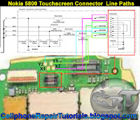
These are the tracing line paths on how to repair a faulty touchscreen navigation issues.To repair touchscreen problem issues needs just little bit analysis unlike any mobile phone repairs procedures. You may proceed in this free tutorial and apply this repair guide if you already do the following method like hard reset, updating or flashing its firmware or by replacing the touchscreen panel pads and make rest assured that the touchscreen replacement spare parts you've purchased is perfectly working and nothing happens or the problem still exists while doing so.
In Nokia 5800 xpressmusic the touchscreen connector lies within on the top side of the printed circuit board,
each X and Y axis have an open tracing spots located near to it.
The repair guide picture below shows the open test spots where a good way to start the check up procedure on that location, it is so easy to trace the line paths from the touchscreen connector since it so very near on that point. Just refer to the refer guide picture and trace each pin configuration where each corresponding X and Y axis is being connected.
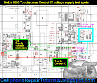
Now, after those parts already been test and calibrated and seems to be okay, you may now proceed to trace and work on the touchscreen control integrated circuit (IC), before removing it or replacing the said IC, check first if the supply voltage that feeds to it is working fine, you may first test the two resistors where the supply voltage line flows. those two resistor seems to be fusible for it has a low resistance value.In Nokia 5800 xpressmusic the touchscreen connector lies within on the top side of the printed circuit board,
each X and Y axis have an open tracing spots located near to it.
The repair guide picture below shows the open test spots where a good way to start the check up procedure on that location, it is so easy to trace the line paths from the touchscreen connector since it so very near on that point. Just refer to the refer guide picture and trace each pin configuration where each corresponding X and Y axis is being connected.
The resistance value is indicated on the repair guide picture below, the resistors value is 10 ohms and the other one is 0 ohms. You may replace those resistors if found open or busted and you may also check the capacitor if it is open or shorted.
You may then now continue to trace the main supply voltage origin or location, the voltage supply origin is located near the power management IC. check if the voltage line paths is okay and then have a test on its voltage if present on that certain point. See the repair guide picture below.
Necessarily, proceed to this step, reheat or reflow the IC then check if it is working.
Remove the touchscreen control IC, and prepare for a replacement parts. But before doing so, while the touchscreen IC is out from the printed circuit board, trace the X and Y line paths from the test spots location near the connector pin way across to the touchscreen terminal or ball bumps. Just check if there are continuity of each line paths unto it. It is so easy to do that even if there is no any cell phone repair guide to follow , just trace each four lines if the connection is working fine. Apply a jumper magnetic wire if you can manage to do on that way. Replace the touchscreen control IC after all of those repair tutorial steps above seem all been done and all corresponding components is working well.


0 comments:
Post a Comment